A An Example Of Hydraulic Directional Control Valve Fig 1b The Axial Download Scientific Diagram

Iso Schemes Of Directional Control Valves

Book 2 Chapter 8 Directional Control Valves Hydraulics Pneumatics

1 Typical Configurations Of Directional Control Valves Download Scientific Diagram

Directional Control Valve Directional Control Valve Mechanical Drawing Symbols Typical Hydraulic Cylinder Control Schematic

Basic Hydraulics Directional Control Valve Blog Teknisi
27 Directional Control Valves.
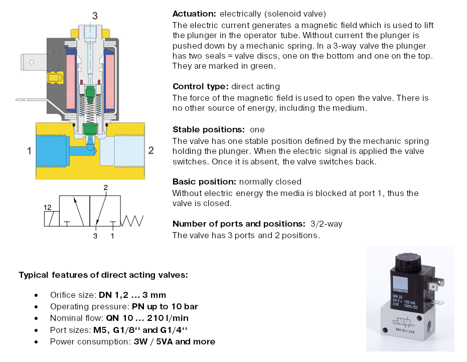
Example of directional control valve. A water faucet allows flow or stops flow by manual control. 2 squares 2 positons 3 ports Number of positions Number of ports. P T A and B.
According to the path numbers of directional control valve we can classify hydraulic directional valve. 34 Filtration and Conditioning. Directional valve structural models.
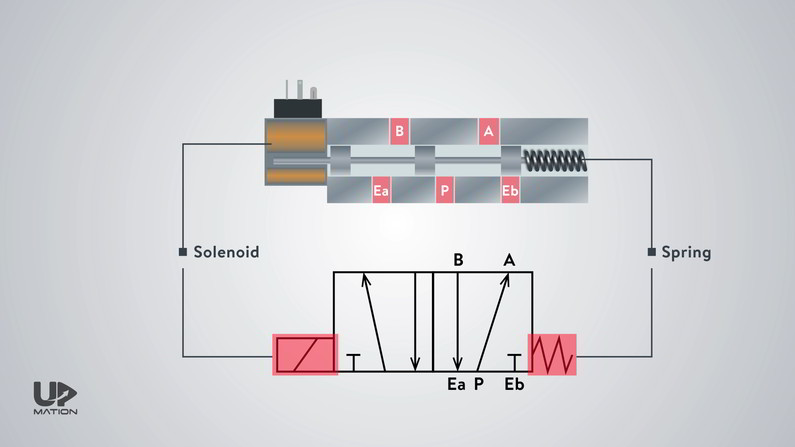
The major function of a directional control valve is to control the direction of flow in hydraulic systems. When the lever is pressed the directional control valve changes its position and controls the fluid flow. There are two-way three-way and four-way types.
A single-acting cylinder needs supply to and exhaust from its port to operate. To be specific valve element controls the movement of valve to close flow or change its direction. A three-position valve is indicated by three connected boxes.
They are capable to determine the path through which the fluid should flow in a circuit. Basics of Directional-Control Valves. The number of.
Mounting configuration according to CETOP R35H ISO 4401 and DIN 24340 Wide variety of spool types including detent and interchangeable spools and bodies. A 3-way valve allows fluid flow to an actuator in one position and exhausts the fluid from it in the other position. Directional control valves are usually designed to be stackable with one valve for each hydraulic cylinder and one fluid input supplying all the valves in the stack.

5 2 Dcv Valve Working Archives Upmation

Iso Designation Of Direction Control Valves Control Valves Instrumentation Forum

What Is A Directional Control Valve And What Are The Types Of Dcv Instrumentation And Control Engineering

Directional Control Valves Working Principle Instrumentationtools

Basics Of Directional Control Valves Hydraulics Pneumatics

Chapter 2 Pneumatic Valves Lecture By Dr Allan

Chapter 2 Pneumatic Component Control Valves Prepared By


Chapter 2 Pneumatic Component Control Valves Prepared By

Book 2 Chapter 8 Directional Control Valves Hydraulics Pneumatics

Intro To Directional Control Valves Lunchbox Sessions

Chapter 2 Pneumatic Component Control Valves Prepared By

3 Way Flow Control Valve In An Isothermal System Matlab