
Cause Effect Graph

Cause Effect Graph Technique In Black Box Testing Javatpoint

Cause Effect Graphing In Software Engineering Geeksforgeeks

Cause Effect Graph Technique In Black Box Testing Javatpoint

Fishbone Diagram Example Templates Free Design Prezi Templates Fish Bone

Cause Effect Graphing In Software Engineering Geeksforgeeks
Cause Effect Graph In Software Testing Examples.
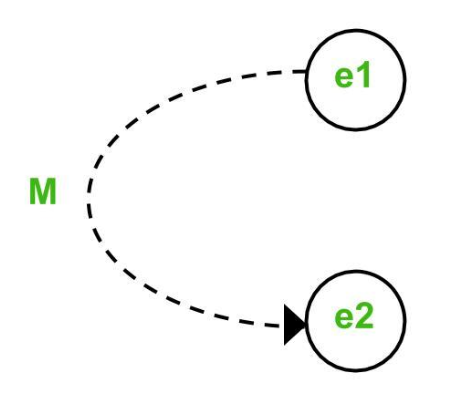
Example of cause effect graph in software testing. Cause Effect Graph Method Part 2 - Types of Constraints - Software Engineering Tutorial Hindi. For example while using email account on entering valid email the system accepts it but when you enter invalid email it throws an error message. The Cause-Effect Graphing Technique is a black box testing technique which captures the relationships between specific combinations of inputscauses and outputs effects.
Com is a great resource. Cause-Effect Graphing CEG is basically a Black-box testing technique that is used to create test cases according to the specifications provided. Primitive Cause Effect Graphs V.
Convert decision table rules to test cases. How to create cause-and-effect diagrams 325. Develop a cause-effect graph.
See the Wikipedia article Cause-effect graph. Cause Effect Graph is a black box testing technique. Transform cause-effect graph into a decision table.
The Causes may be thought of as input and the effect is thought of as the output. It is generally uses for hardware testing but now adapted to software testing usually tests external behavior of a system. From our free online course Practical Improvement Science in Health Care.
According to Myer Cause Effect Graphing is done through the following steps. It deals with specific cases avoids the combinatorial explosions. Cause and Effect Graph in Black box Testing.

Cause Effect Graphing In Software Engineering Geeksforgeeks

The Ultimate Guide To Cause And Effect Diagrams Juran

Cause Effect Graph Technique In Black Box Testing Javatpoint

The Ultimate Guide To Cause And Effect Diagrams Juran

Cause Effect Graphing In Software Engineering Geeksforgeeks

The Ultimate Guide To Cause And Effect Diagrams Juran

Fishbone Diagram Tutorial Cause And Effect Fish Bone Ishikawa Diagram

Fishbone Diagram Template For Marketing Diagram Ishikawa Diagram Fish Bone

Demo Start Graphic Organizers Cause And Effect Cause And Effect Relationship

Low Satisfaction Fishbone Free Low Satisfaction Fishbone Templates Fish Bone Customer Satisfaction Satisfaction

Cause And Effect Diagram What Is A Cause And Effect Diagram And How To Make One

Fishbone Ishikawa Diagram Template For Root Cause Analysis Tulip Ishikawa Diagram Ishikawa Word Template

How To Use The Fishbone Diagram In Your Ppt Templates Fish Bone Risk Management Brainstorming Activities

